"Want To Layout Stairs
The Way The Pro's Do It?
Then Study This
Stair Layout Primer!"
This stair layout primer will teach you how to correctly calculate the rise and run for any given circumstance where a set of stairs needs to be built. Your success in building a first-class set of stairs begins with knowing how to calculate the rise and run for a given set of circumstances so that you stay within the minimum and maximum guidelines of most modern building codes regarding safety and headroom issues.
Before we go into the calculation and layout procedure in this stair layout primer, lets first take a look at what the most recent building codes require for stairs. The Residential Building Code—Stairs: is a municipal regulation. It varies from each town, county and state in the U.S.A. Canada has it's own variations taken from similar building codes.
Some jurisdictions base their legislation on the 2000 and 2003 International Residential Code (IRC). Other communities are still using the 1997 Uniform Building Code (UBC). In all cases, each jurisdiction has amended the code recommendations to reflect local concerns and customary usages in their jurisdiction regarding stairs. In some cases, a local jurisdiction will limit the rise and run for treads and risers outside the maximums and minimums recommended in the code they are using.
It is absolutely essential that you check with your local building department FIRST, as the following information in this stair layout primer is only offered to suggest reasonable and prudent guidelines based upon historical usage and design of stairs, and is a composite of the various building codes in use today in North America.

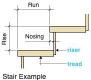
The Stair Example Diagram at the left is a fair visual reference for the following minimum and maximum dimensions that are in the various codes today. Refer to it as you read the following to get a visual representation in your mind of what the specifications are stating. It is always best to know in advance what the code requirements are before you cut a piece of wood and possibly waste it because you have to make a change after the fact of inspection.
Nosing Extension:
The maximum overhang for nosing is somewhere between 1-1/4" and 1-1/2". Some jurisdictions legislate a minimum of 3/4" including floors and landings.
Riser Heights:
The maximum of between 7-3/4" and 8-1/4" and some jurisdictions regulate a 6" minimum riser height.
Run Lengths:
Minimum of between 9" and 10" (does not count the nosing) with a note that runs over 10-1/2" will most likely require three (3) balusters per tread to comply with the 4" maximum opening between balusters under child safety guidelines.
Dimensional Variations:
Can only allow 1/4" to 3/8" variance in height and width from one riser or tread to either adjacent riser or tread.
Stairway Width:
A minimum of 36" with a stipulation that allows a wall mounted handrail to project from each side a distance of 3-1/2" (on each side) into said width.
Headroom Clearance:
A minimum of 6'- 8" clearance measured from the outermost portion of any tread nosing on a plumb line upwards from said tread nosing.
What we recommend in this stair layout primer is that the most prudent approach you can take regarding building code requirements is to check with your local jurisdiction first before you order any lumber or begin your layout work for stairs. You may be surprised at how helpful they can be — so give them the opportunity to serve you. Find out what they know and let them explain to you the code variations they have adopted. If they have any literature handouts concerning stairs and their requirements — accept them and study them closely to make sure you understand what they will be looking for at inspection time.
If you attempt to bootleg a set of stairs in without a building permit, you open yourself up to a indefensible lawsuit in the event someone is hurt or injured while using your stairs. So get the building permit as insurance and accept any help the inspector offers concerning stair design requirements. Now lets look at how to calculate and layout a set of stairs.
Stair Calculation and Layout:
Over the years, and in gathering information for this stair layout primer, your editors have noticed that adding a set of stairs to a garage (or other location) always comes down to the same two conditions about 85% of the time. So, in this stair layout primer, we will illustrate both of these conditions for you since one of them will probably be what most of our readers encounter.
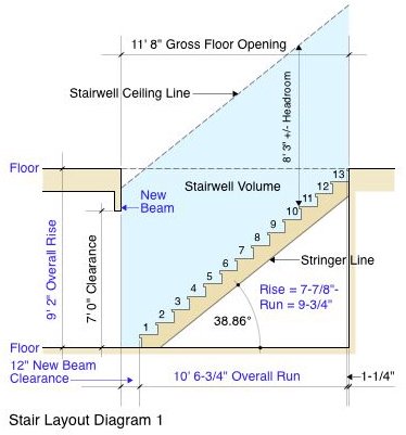
Stair Layout Diagram 1 below illustrates the situation you will encounter in about 50% of all projects. Study it for a few moments to familiarize yourself with the conditions.

This condition assumes you will have to remove some floor joists in order to create the stairwell volume between each floor. In this scenario, the floor joists that need to be removed will be running parallel with the direction of the proposed stairs. Since many homes and garages are built from two (2) 12' deep bays, the gross opening you create by removing some floor joists will be about 11' 8" on average.
Often, whatever structural element that was supporting the removed floor joists (and those remaining), such as a load bearing wall, has to be removed also, so a new beam has to be inserted for the remaining floor joists to bear upon. In some cases, this could be an existing wood or steel beam that must remain. We are illustrating it as a new beam, but it could be either. The point we are trying to make in this stair layout primer is that it will play a major role in headroom clearance for the new stairs, and how many treads and risers you can fit in the stairwell volume.
We determined that we would need 12" of clearance between the inside face of the new beam and the outer edge of the nosing on Tread 1 in order for a 6' 4" tall person to easily negotiate the first step without having to duck for fear of colliding with the bottom edge of the beam when descending the stairs. Once we determined that criteria, we determined that our overall run would be 10' 6-3/4". Our overall rise between floors is fixed at 9' 2".
As a preliminary step in this stair layout primer, we estimated that we could have 14 risers (13 treads) in our new set of stairs. So we converted our overall rise of 9' 2" to inches which equals 110" and divided that by 14 risers as follows: 110 ÷ 14 = 7.8571". If you convert the decimal .8571" to sixteenths of an inch it works out to a shy 7/8". So we would have a riser dimension of 7-7/8"-, with fourteen (14) risers which is within acceptable code limits.
With the riser dimension in mind, we next calculated what the length of our individual tread run would be by taking the 10'- 6-3/4" overall run distance and converting it to inches which equals 126.75". We then divided that by the 13 treads in the staircase as follows: 126.75" ÷ 13 = 9.75" or 9-3/4" which is within acceptable code limits. We then determined the angle that our staircase would sit at above the lower floor as 38.86° which is well within acceptable code limits. (See our page Stair Types for a demonstration of how to calculate the staircase angle with a scientific calculator).

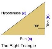
Now we need to know what length lumber we will need for our stair stringers. In this stair layout primer we will calculate this using the formula a² + b² = c² as it applies to the right triangle shown at the left. The "a" leg is our overall run in Stair Layout Diagram 1 above; the "b" leg is the overall rise minus the depth of one riser (7-7/8"); and the "c" leg (the hypotenuse) is the length we will be solving for. Here is how we go about this:
The overall run of 10' 6-3/4" = [126.75" x 126.75"] = 16065.5625 inches squared. The overall rise of 9' 2" minus 7-7/8" (one riser dimension) = 102.125" x 102.125"] = 10429.5156 inches squared.
Now we add the squared versions together as follows: 16065.5625" + 10429.5156" = 26495.0 inches squared. We now have to get the square root of this figure as follows: √ 26495.0 = 162.7728". That figure reduces down to roughly 13' 6" so you will need 14' long - 2 x 12 stringer material for the project illustrated in Stair Layout Diagram 1.
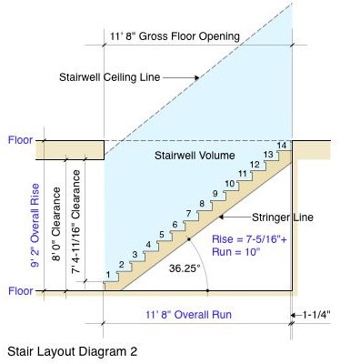
Stair Layout Diagram 2 below illustrates in this stair layout primer the situation you will encounter in about 35% of all projects. Study it for a few moments to familiarize yourself with the conditions and compare it to Stair Layout Diagram 1 above.

This condition occurs where there is no new beam needed at the beginning of the staircase on the lower floor. The reason no new beam is needed, is due to the fact that the floor joists are running perpendicular to the staircase direction and all of the support work will be along one or both lengths of the staircase where the joists will be cut to form the stairwell volume.
This situation allows for an even more graceful set of stairs to be constructed because we can get one more tread and riser into the stringer layout which ends up reducing the angle of rise above the floor to 36.25°. As shown in this stair layout primer, the stair stringers will span the entire 11' 8" gross floor opening of the stairwell volume with no headroom problems at Tread 1.
In this situation we determined that our treads could be a full 10" which equals our 11' 8" overall run and gross floor opening. Our overall rise was the same 9' 2" as shown in Stair Layout Diagram 1 above, and with one more riser in the stairs reduced the individual rise at each riser to 7-5/16". We used the same calculation technique as discussed above for Stair Layout Diagram 1 to determine these dimensions.
Our actual stringer length in this case will be about 14' 6" so we would need 16' long 2 x 12 material to build the stringers from. We used the same formula as discussed above to determine this dimension.
The purpose of this stair layout primer is to illustrate how to calculate the layout of a set of stairs for any given situation and to show the reader that under small conditional changes (no new beam needed) in the same sized opening, two different sets of stairs can be constructed. Your editors recommend that you always layout any set of stairs for the smallest angle possible within code limitations.
Next, study our page Stair Stringer Primer to learn how to use the framing square to layout the stair stringers.
❖ Testimonials ❖
We have been following your blog and we have found a lot of useful information in it.
Cecil Sibanda
Product Coordinator
Dorman Products, Inc.
Colmar, PA
I was pleased that I was able to easily find the proper tall storage cabinet for my garage. I needed lockable storage to keep my toddler away from sharp tools and solvents that my husband stores. Garagetips-101 solved my problem!
Renee M.
I love the detail in your garage building pages. They helped me understand how to engineer a foundation for a garage we are planning that our building department will approve. I had the inspector go to your pages and review what I was talking about. Now, I am studying the wall framing sections, as we plan to build it ourselves this fall. Thank you so much for the great information.
R.G.,
Des Moines, IA
Great stuff on wall framing. I never really understood the on-and-off spacing concepts for the wall studs until I read your explanations.
Will,
Grand Island, NE


